|
Beside
modelism, I do a lot of military flight simulation and building a full working
cockpit was a goal I set some years ago. Finally, I decided to have a go at it
by starting the construction of the AcesII seat since the cockpit will be a
Viper MLU pit. The seat was done in wood, aluminium sheets, resin, plastic parts
and a lot of products and techniques I used in my modelling hobby. The idea was
to build a full scale model in scratch that I could use for my simulation hobby.
Since the beginning, I considered this advendure to be part of my modelling
experience.
The seat was done is four steps.
First the seatpan, then the back rest with the head rest plate and finally
assembling, detailling, painting and wheatering. You'll see I used some resin
after marked goodies for the seat but unfortunately, I couldn't find
photoetched parts  !
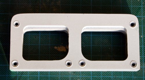
I did made some aluminium parts on a mill and a lathe though! !
I did made some aluminium parts on a mill and a lathe though!
The
drawings I used as basic references are the ones made by Speedone (A dutch
fellow who probably started the first Aces2 reproduction) His set of drawing was
modified to suit my needs. As reference I
used the verlinden lock-on book on the F-16 and the well known Daco book on the
F-16. The wood I used is MDF 18 and 12mm. Aluminium are 0.5mm
sheets. I also used some real parts I found a little everywhere on the Web.
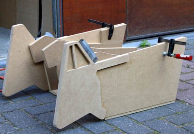
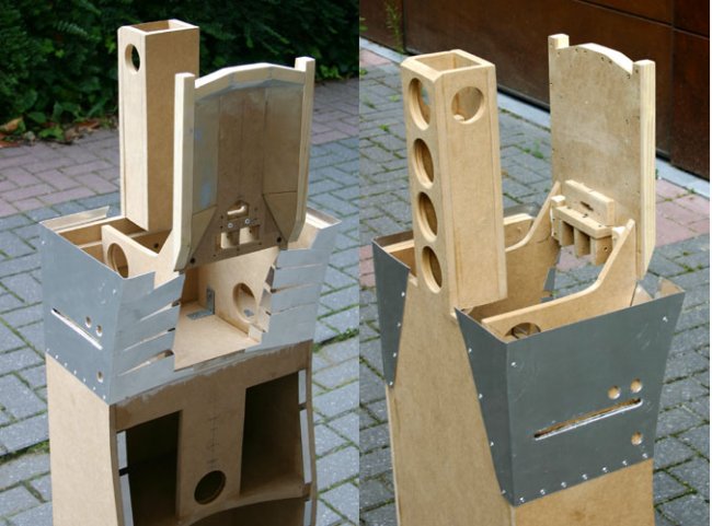
Part 1: the seatpan:
The seatpan construction was
straightforward. Only minor modification to the published drawings were
required. it is done in three parts, the main body and two sides. Needless to
say, a lot of sanding was required to have the same curves on all the vertical
frames. Assembly is done using white glue and screws as seen on the picture below.
The two sides are simply two layered wood parts featuring the knee protection
of the seat. These were sanded so the edges were smoothed
- they will be detailled later.
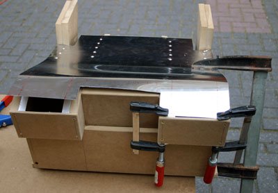
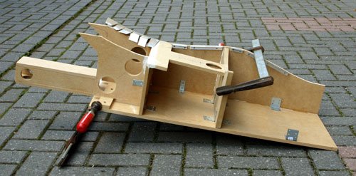
The seatpan top has been done in aluminium (easier to bend than wood) and
riveted on the metal guide I placed on top of the vertical edges of the
seatpan. First time I used real rivets in a model
I made the mistake of cutting the sheet before placing it. So I had to fill
some gap with mastic....
Part
2: the back rest:
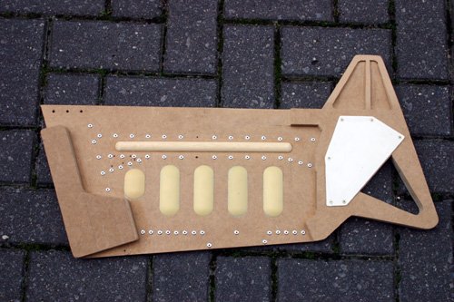
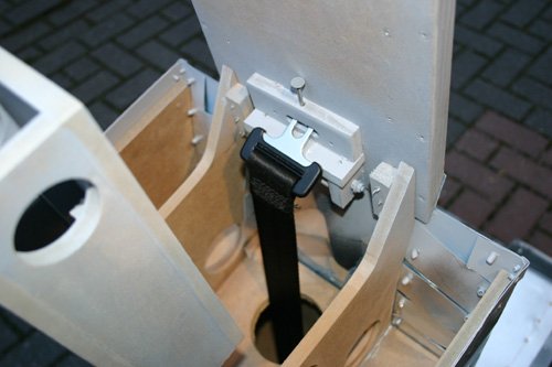
The
back rest was much more complicated than the seat pan. Different challenges
were foreseen such as the
placement of the seatbelt mecanism, the three axis curve of the aluminium
sheet and the headrest buiding-
probably the most complicated part of the seat. The body was assembled first
using mainly white glue and screws. A thin metal plate was riveted on top of
the lateral side for easier detailling. It will also nicely blend the
parachute container with the main body of the backrest.
The headrest was made in wood as well using some part heavily sanded in
different plans and a lot of modelling filler :) Even plasticard were used.
The roller mecanism is made out of wood cylinders
turning on a common axis. They are inserted in a small assembly which is glued
on the back side of the headrest.
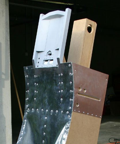
It
was really tricky to place the large sheet of metal on the back rest because of
the multiple curves in three different plans. But starting in the middle and not
cutting the sheet before placing was the trick to get a good result. I also heat
formed the sheet with quite a powerful hairdryer! When
correctly riveted, the metal sheet was cut with a cutter along the wood panels. The
headrest was finally placed on top of the mainbody.
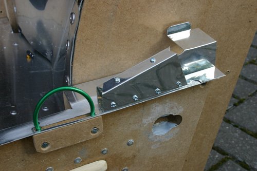
Part 3: detailling:
Here's
the part I loved the most - nothing really surprising from a modelism point of
view! The side panels of the seat needed extensive detailling to make all the
tiny parts and handles. It was quite comparable to go fishing for parts in the
scrap box. Except that I fished in hardware shops and in leftover metal parts.
It is also here that some parts were cast in resin (with the help of a
friend). The cable system on the side of the backrest was found in plumber
hardware while the rollers were machined on the lathe from an 50mm aluminium
cylinder. The seatpan sides were detailled using the resin bumps, rivets and
a sheet of plasticard for making the white part below the knee protection. The
emergency release handle was done in PVC and machined on the mill (quite
bigger than my proxxon mini mill) as are some other pieces such as the seat
arm lever, ...
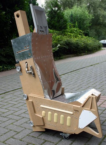
At
this stage, here's what the seat looked like: The seat is not inclined properly
yet. I also took the liberty to install it on 2 wheels because obviously, it's
not lightweight.
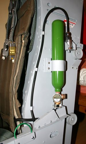
The
seat arm lever will depress a microswitch that is wired to the computer
through an X-key controller. That will allow me to make interaction with the
flightsim through programming the keystrokes. The oxygen system is done in
scratch as well
using sheet of metal. whenever I have to make a metal part out of the aluminium
sheet, I first make a paper template and bend according to the drawing. if the
part fit, then I cut the metal sheet and bend it. The seat shoulder straps will
be attached to a car seatbelt mecanism placed inside the seat. That will allow
the seatbelts to reel inside the seat as in the real deal.
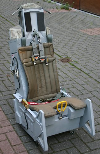
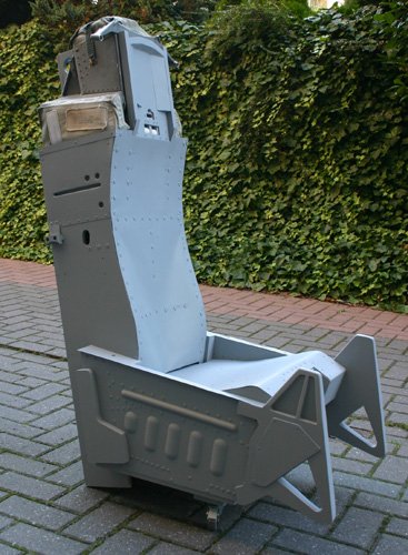
Part 4: painting
and decalling:
The
seat was primed in white and a coat of gull gray was sprayed afterwards. A
coat of varnish was then sprayed as well to protect the paintwork from future
abuse. The decals were done with the computer and printed on sticky white paper.
Before gluing them on the seat, a clear sheet of transparent plastic was applied
as well. The seat was then wheathered using dark aluminium paint (for the paint
chips) and some darker washes of brown and black paint. Instead of drybrushing,
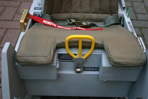
I sprayed some strategic spots with a lighter gray. When all was done, the black
cables were placed as all the pending details such as the ejection handle (that
is interconnected to the computer as well.) The cushions and belt (real parts)
were placed...and I was finally able to seat in it
It
has been a thrilling 4 months intensive experience between a 1:32 F-16 and a 1:48
Spitfire. I learned a lot of new techniques solving the problems I encountered.
But I must confess, my modelling experience helped me a great deal in the
building of my first 1:1 model. I also have to thanks a lot of guys having
helped on this project!
Olivier
|