|
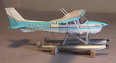
Minicraft's new
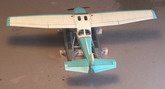
Cessna 172 Floatplane is a fine addition to their series of General Aviation
kits, notably the Beech Bonanza, and Piper Super Cruiser/Cub.
However, I found an incredible engineering blunder, that seems to have gone
unnoticed by anyone to date. I began this build by gathering reference. There
was a wealth of 172 floatplane reference online, which I copied to my files, and
printed out. One detail that really caught my eye was the system of steering
cables and pulleys that are linked to the aircraft's rudder. These allow
the pilot to steer the pontoon's (floats) rudders while taxiing. There was a
virtual spider's web of cables aft of the cockpit. I printed out some closeups,
& headed to my brother Paul's house for some photo interpretation help. Paul
is an FAA certified Airframe & Powerplant mechanic, on top of being a
crackerjack modeler. We determined the system worked exactly like those on an
old outboard boat of the 50s, and 60s (before hydraulic systems) and was an
extension of the plane's aero-rudder, connected on either side by a lenghtened
replacement horn. We also figured out a second bridle-like set of cables was for
the retraction of the rudders. The kit's float rudders are molded to the float
in the 'up' (retracted) position. That is reasonable, as the ONLY time they are
in the down position is taxiing to/from the shore, or in lining up for takeoff.
Click on
images below to see larger images
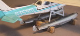
After making my
diagrams, I began laying out the fuselage sides, struts, and floats so I
could get a rough idea of where the pulleys (needle heads) should be
positioned. This is where things suddenly hit a proportional stone
wall...NOTHING made any sense, and the kit's floats were way too far
forward or short for the cable angles. This was obvious in all
the photos. I emailed Paul, & he suggested I look up EDO, the float
manufacturer's site. I did so, & there was another gold mine of
information, but it still didn't explain the seeming mistakes of the model
parts' size/positions. Then I suddenly saw it, the model's struts were
facing the WRONG DIRECTION! It wasn't just an error in the instructions,
but an engineering error too. Minicraft had put round pegs & hole on
one end, square ones on the other to make them 'idiot-proof'. If that
wasn't enough, they made the float's front, and rean attach point
recesses different sizes. Even the box art was wrong! The ONLY
diagram that showed the struts facing in the correct direction was the 3
view drawings for decal placement. On the otherhand, if you flipped
them over, they jived with all the photos (of REAL airplanes), & the
cable pulley positions suddenly made sense. The diagonal strut should
attach to the fuselage where the main gear anchor, & the structure is
reinforced. The struts would be correct if this were a model of a Cessna
180/185 which are tail-draggers & the main gear attach right behind
the firewall, but it's ass-backward for a 172! The EDO site, & EVERY
photograph online completely supported this. With a few minor
modification, this was correctable...thank the modeling gods.
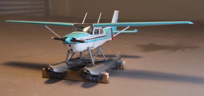
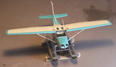
Beyond the strut
fiasco, the kit is very nice, with recessed panels, etc. The float rudders are
thick, and simplistic, so I cut these off, then scratch-built the
rudders, and their hinges, and steering horns. Footsteps at the firewall,
along with the handles on the top of the firewall were added. These allow
one to reach the fuel tank caps on the top of the wing. There's also two hard
point rings attached to the main spar, which allow the aircraft to be lifted out
of the water. These were made out of solder & glued into place. All float
equipped 172s also have a firewall 'V' brace installed that connects the
firewall to the wingspar behind the windscreen. This was made of straight
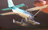
pin sections. While I was there, I put in sun visors for good measure. Another
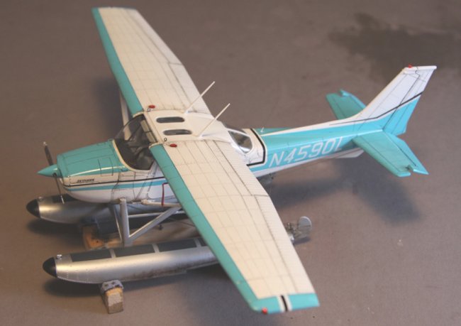
addition is the ventraI dorsal, found on a good number of float equipped 172s. I
also added common whip antennas at the sides of the vertical stab, and
starboard aft fuselage top with stainless wire. I didn't like the kit's decal
options/colors, so I found a scheme from the late 60s, got out the
masking tape, and black pin stripe decals. I had a sheet of Draw Decals'
Cesssa slanted letters for the registration. Model Master painted were used, except
for the floats which were done with Alclad Aluminum. Bobe's EZ-Line
was used for the steering cables.
Photos by Henry Popp
Michael Presley
Click on
images below to see larger images
|
|