|
The X-15 needs no introduction. There are several plastic X-15s on the market, but they are all either expensive and/or contain errors. Perhaps the best kit available is a 1/32nd scale card model designed by Ken L. West. It is of the X-15A-2, the stretched version of 66671, the vehicle that would go on to set a speed record of 4,520 mph (7,274 km/h) in October 1967.
Aside from its speed record, the X-15A-2 was kind of a dog (numerous failed or aborted missions) and I've always liked the looks of the shorter X-15 anyway. So I decided to convert West's 'A-2 into its predecessor, the X-15-2. I shrunk it from 1/32nd to 1/48th.
The major change involved cutting a 28-scale-inch chunk out of the fuselage, as well as a similar length from the chines. The challenging part is you have to trim the chines in a different location than the fuselage. I shortened the fuselage by cutting off 1.5cm of the center section where the fuselage was extended to house a liquid hydrogen tank on the real 'A-2. I then assembled the chines and figured out where they needed to be shortened. I also had to fashion new end pieces for the chines, as they differed from the ones on the 'A-2.
|
Click on
images below to see larger images
|
|
|
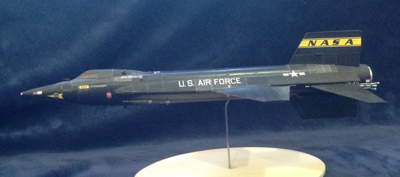
I wanted to model 66671 as it appeared in the summer of 1962, before the November hard landing that led to its conversion to the 'A-2. X-15 markings could vary widely from mission to mission and vehicle to vehicle. References are a must. On the fuselage, the location of the "U.S. AIR FORCE" legend could vary, as could the location of the national insignia.
On the dorsal stabilizer, the yellow NASA band could be on both sides of the rudder or just one side or neither. Similarly, some flights had the serial number on both sides of the fixed portion of the dorsal stabilizer, while others just had it on one side. Still others carried the serial number on the rudder; it could be on one side or both. Like the "NASA" in the yellow band, the font of the serial numbers could differ from flight to flight.
The wings could carry both the national insignia (left wing) and USAF (right wing) or just the national insignia -- or no markings at all.
In the summer of '62, 66671 had the yellow NASA band on the left side of the dorsal stabilizer but not the right, and it carried the serial number on the right side but not the left. The wings were devoid of any markings, except for the "Beware of Blast" warning on the right wing only.
I modeled the tail markings by cutting apart the kit pieces and mixing and matching pieces and assembling them into the tail. The dorsal stabilizer/rudder is modeled as one structure, so I improved the accuracy of the model by splitting the dorsal stabilizer into the fixed portion and the rudder. On the real vehicle, there is a gap between the fixed and moving sections; you can see daylight between them. For this model, the wing markings were removed electronically.
My additions/modifications/corrections to the kit, from fore to aft:
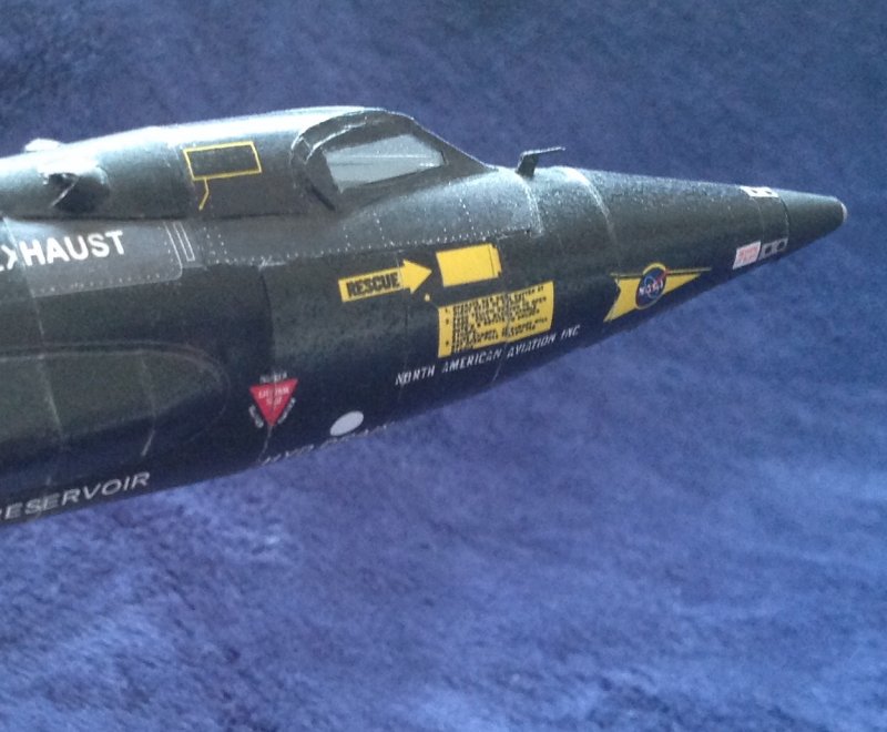
-- The fuselage nose piece immediately behind the Q ball was replaced with black card, using the kit piece as a template;
-- Cockpit windows were changed from ovals to the proper pre-stretch shape;
-- The kit piece for the section immediately aft of the cockpit was replaced with black card, using the kit piece as a template;
-- Bug-eye camera housings were scratchbuilt, and cameras added;
-- The liquid oxygen vent on the top of the fuselage was detailed;
-- Replaced the various kit drains with smaller, more accurate ones made from wire coating;
-- The fuselage was shortened 28 scale inches;
-- The chines were shortened 28 scale inches;
-- Strenghthening strips were added to the wing-fuselage joint, as on the real vehicle;
-- A gap was added to replicate the gap between the fuselage and wings forward of the first panel line on the wing, as on the real vehicle;
-- The fixed and moving sections of the dorsal and ventral stabilizers were split and a pivot added to replicate the gap between the two;
-- Plumbing on the back of the rudder was replicated with wire;
-- The horizontal stabilizers were altered to reflect the accurate cross section;
-- Pivot points were added to the horizontal stabilizers to replicate the fuselage-stabilizer gap seen on the real vehicle;
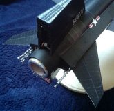
-- A new engine rear section was built from black card, using the kit part as a template;
-- The end piece of the rear engine section was inset to improve accuracy;
-- The chine extensions at the rear were removed and new end pieces were made from black card;
-- The shape of the stowed landing skids was altered to more accurately reflect those on the vehicle;
-- Silver card was used to model the exterior housing of the XLR-99 rocket motor, using the kit parts as templates;
-- Replaced the parachute cover on the section of the tail jettisoned before landing;
-- Weathering was done with black and gray artists' pencils.
I need to thank Ken L. West for designing a great model. John Bowden also helped out. Research on markings by Jeffrey Kubiak of Hypersonic Models was invaluable. It feels good to finally add this important research vehicle to the collection.
David Hanners
|